Hardware
Software
Details
To do that we will have to process step by step in order to:
1- identify the required connections, mainly the power supply inputs and the decoder logical output,
2- define the optimal printed board cut line to extract the DCF chip.
The clock case must be firts opened to access the printed board. The hard part of that work will then start. We need to identify the chip external pin-out. We have to look for:
- power supply input (2 lines),
- raw DCF signal output (1 line),
- output-enable input (1 line).
We can easily find the DCF77 chip by looking for it near the ferrite rod wires terminations. Around it are lying one or two SMD ceramic capacitors. The ground path on printed board let us quickly find the related chip input pin.
The next step requires we power on the clock and probe around the DCF chip connections using a voltmeter or a scope:
- The decoder output can be search by looking for a 1s pulse signal.
- The power supply input is found by following the clock power path.
We then have to identify the 'output enable' signal used by the clock chip to control its synchronization. The best way seems to cut one by one the unidentified wires until the pulse output cease.
We can now solder connect 4 thin wires located as near as possible from the DCF chip.
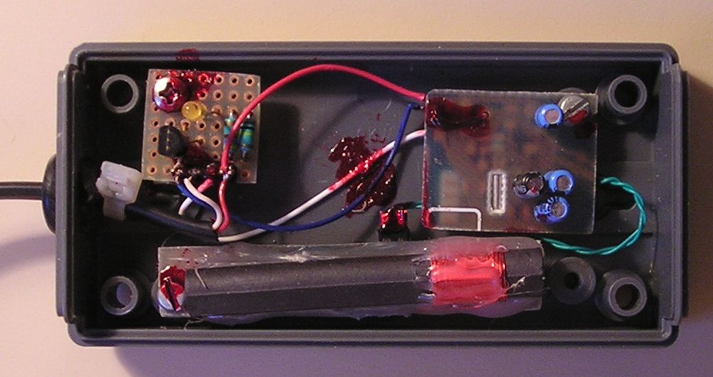
The cut line can be draw using one of those super fine permanent slide pens. The DCF chip has to be extracted from the printed board by cutting it with a small saw. Do not forget that these chips came with some external components: one or two SMD capacitors and the ferrite rod antenna.
The resulting board can be housed in a small plastic case but not before we had tested it by connecting it to a PC. If the serial line is to be used, provision must be made to adapt the RS232 power supply level to the one required.
The best way is to use the joystick/MIDI connector which provides a 5V supply and the required TTL logic input. We can convince the Windows operating system that a legacy joystick has been connected by supplying the analog X and Y input a 2.5V level. This can be easily done through a resistor bridge connected between ground (DB15 pin 4) and the joystick power supply (DB15 pin 1).
The DCF77 decoder output is connected to the Push Button N°1 input (DB15 pin 2).
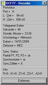
Connecting our device leads Windows to automatically load the joystick driver. The DCF77 signal pulse can be verified through the game controller properties window. The button 1 icon will then pulse accordingly to the DCF77 signal.
For more information, take a look at the very nice connection schematics on the IN3HER site.
Pictures
| The IN3HER software | The DCF77 chip part of printed board | |
 |
 |