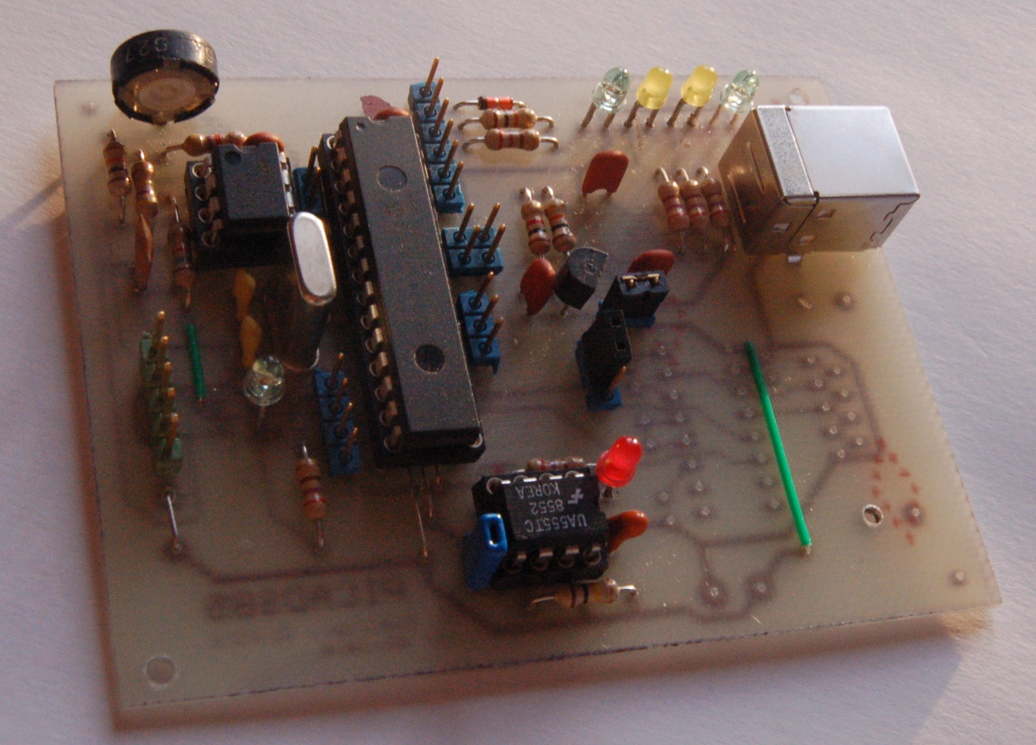
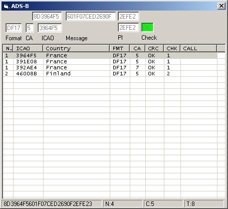
It uses a PIC18F2550 to decode ADS-B pulses received by a modified SAT tuner and demodulated by an Analog Device AD8307 log amplifier.
I tried to keep it as simple as possible and spit it in three parts.
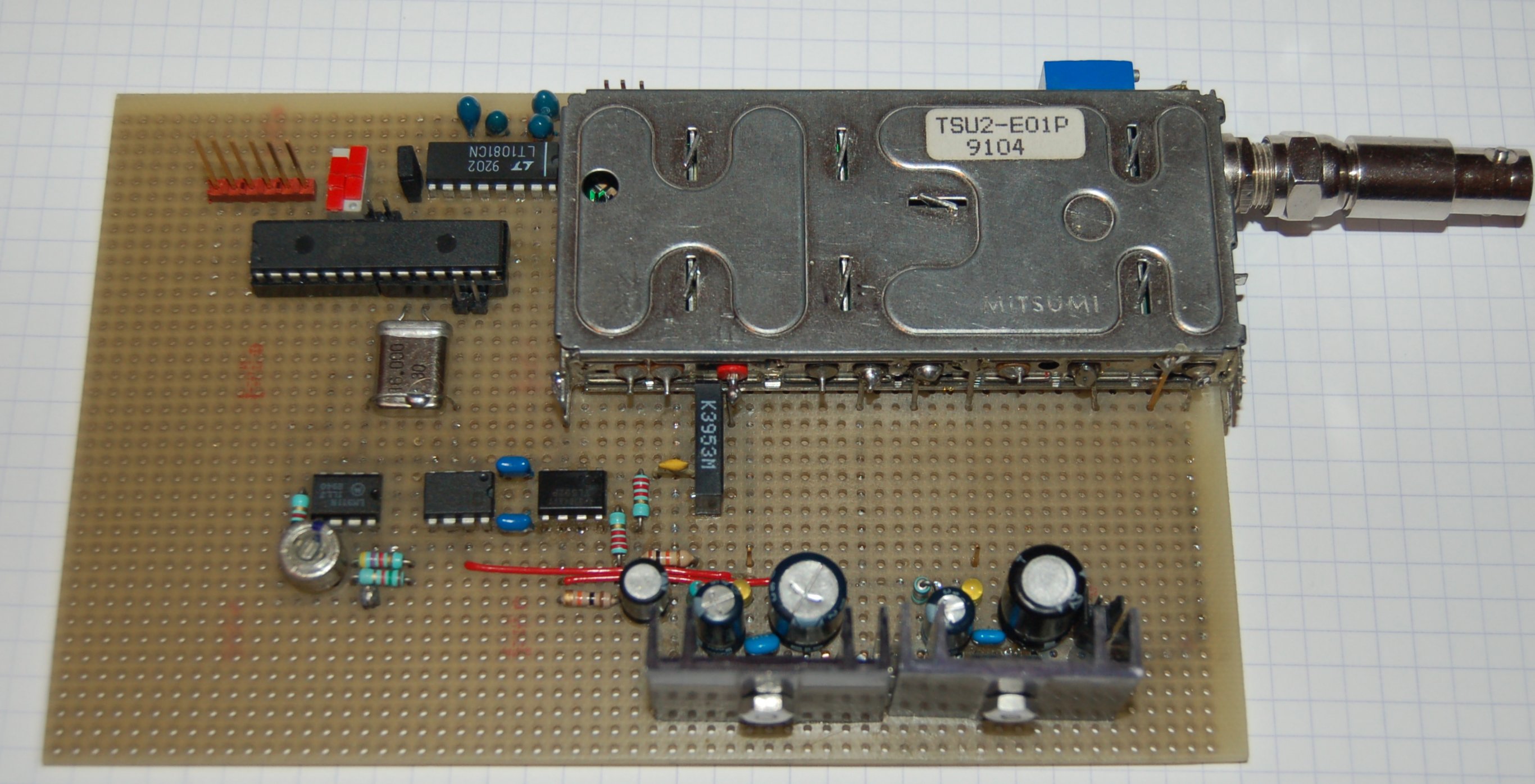
- A home made receiver front end which converts the 1090MHz carrier pulse modulation signal to a low frequency logical signal,
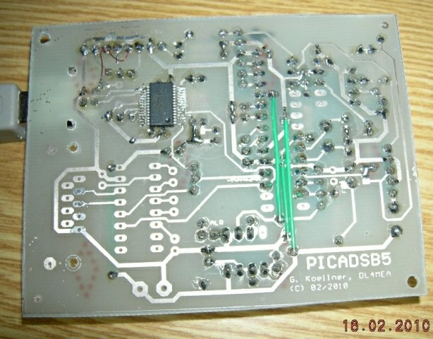
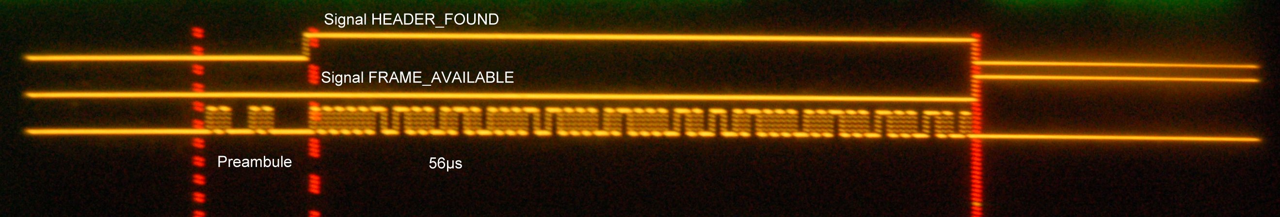
- A µprocesseur decoder which decodes the logical signal and converts it to its hexadecimal representation, or more,
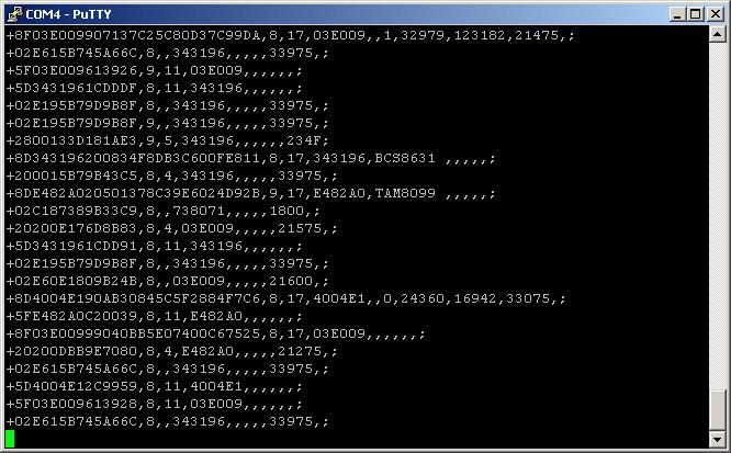
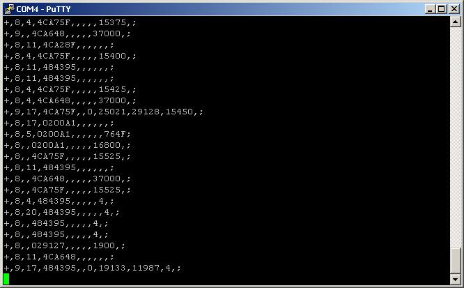
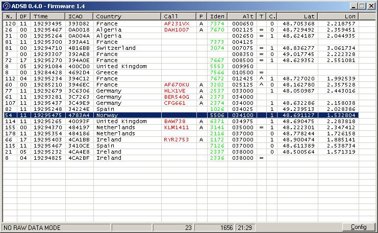
- A Windows program that will display the basic data send through the decoder serial output.
The decoder output format as been integrated in the well know Plane Plotter application enabling anybody having completed all or parts of that project to display the ADS-B / MODE-S collected data.
Receiver front end:
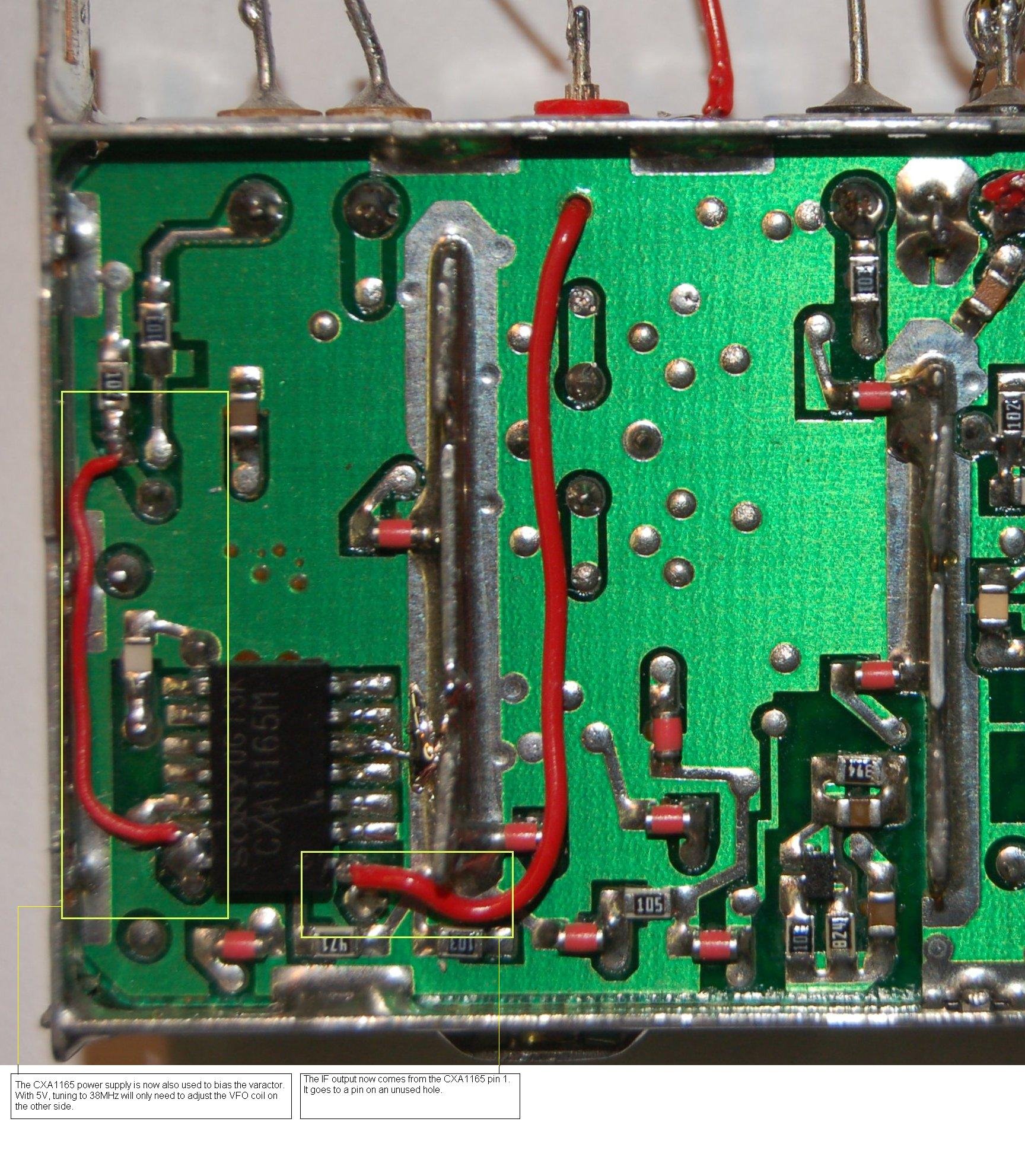
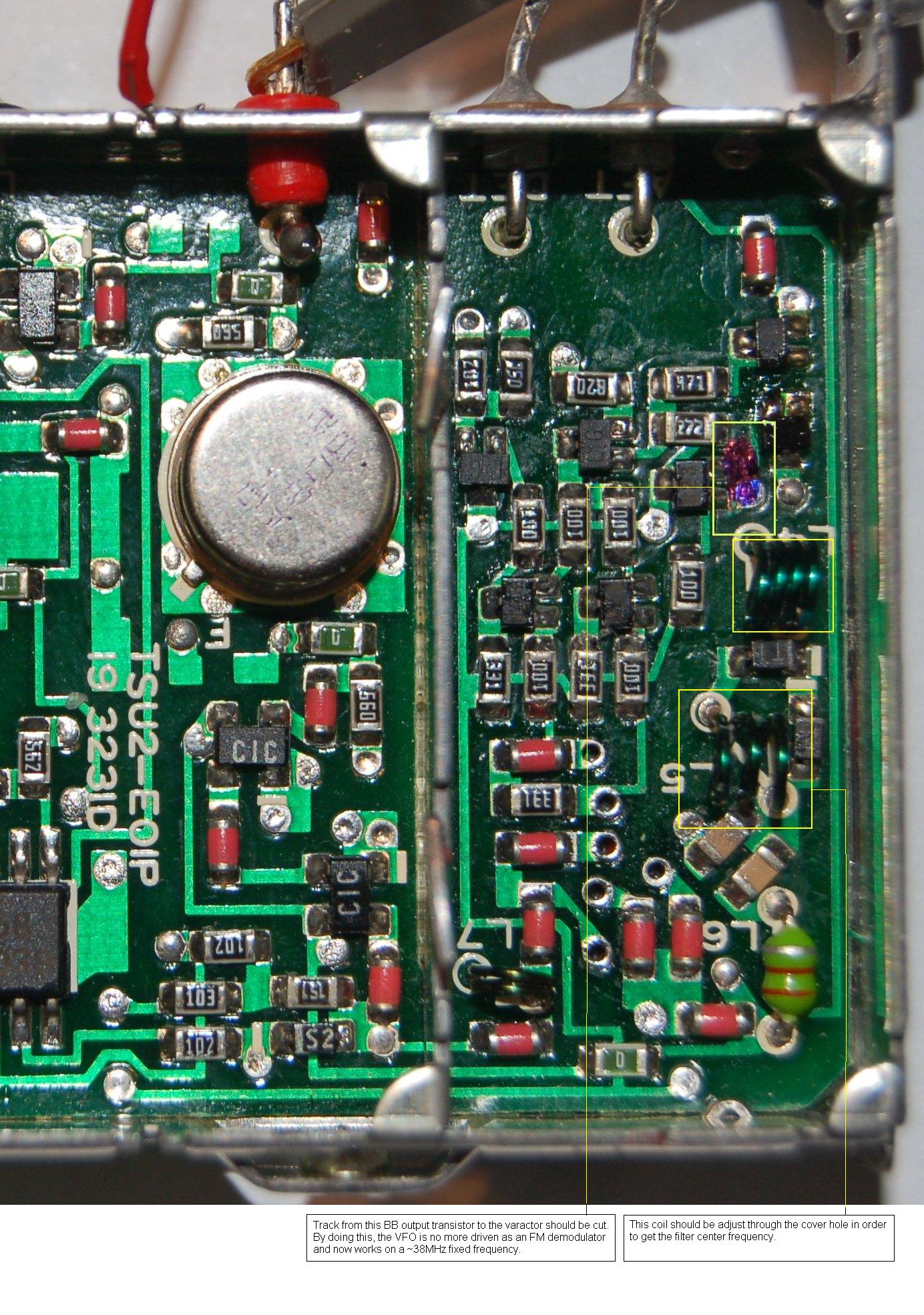
| VFO modifications & IF ouput | VFO modifications | ||
 |
 |
However, any other design can be used if it provides either: