Hardware
Software
Details
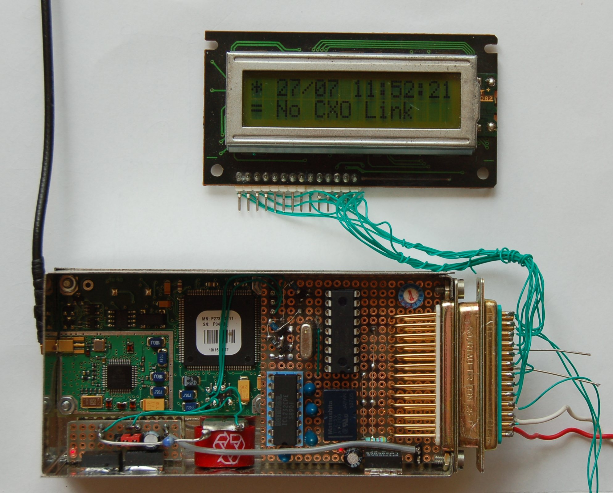
Having at my disposal an unused 'OscilloQuartz' 10Mhz OCXO and a Motorola Oncore MT12+ timing GPS module, I decided they could became parts of a GPS locked frequency standard. I opted for the VE2ZAZ design for the GPS part mainly as the source code was available. It could be modified if needed.
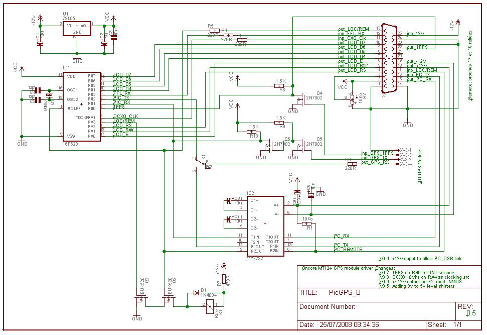
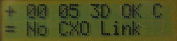
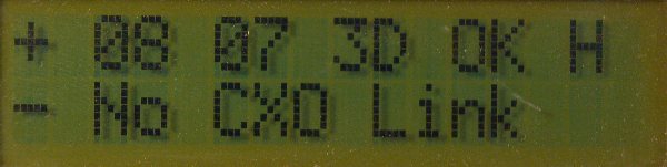
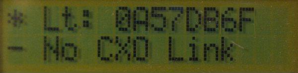
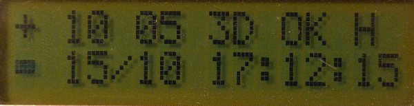
As I do not want to be dependent on my PC to display some useful information I decided to design a dedicated PIC control module. This module is able to display GPS information such as status, latitude, longitude, height, date and time to the first line of a 2x16 charecters LCD display and the VE2ZAZ OCXO control module status on the second line. It has been designed handle the Motorola Oncore MT12+ (timing) GPS module: initialization sequence and status message - the @@Hb sequence - decode.
Starting with the V1.3, it can decode the NMEA 'GGA', 'GSV', 'GSA' and 'ZDA' frames. It can also initialize the Motorola MT12 and the Rockwell Jupiter GPS modules to use NMEA mode. The VE2ZAZ status decoding can now be disabled for those who only wants to decode GPS status. In such a case, GPS status is displayed on first display line, the other information are displayed one after other on the second line. Take care that these new functionnalities have been simulated and not tested as I do have MT12 or Jupiter GPS at hand. The MT12+ I have do not allow switching to NMEA mode as its firmware dedicated to timing measurements.
.
Two versions code are provided:
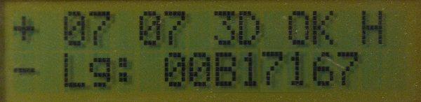
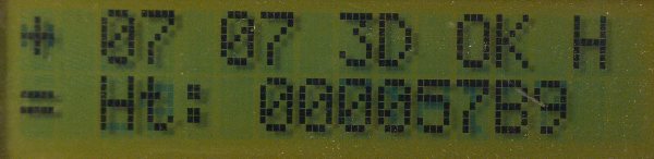
- a PIC16F628A version which contains the dedicated Motorola MT12+ binary decoder but displays location information in hexadecimal code as it does not have enough program space to convert it to coordinates. The VE2ZAZ status decoding can be disabled when needed.
- a PIC16F648A version which includes all the features: MT12+ Binary or NMEA decoding and initialize, Rockwell NMEA decoding and initialize, and finally NMEA decoding only. The MT12+ binary mode, which is selected by default, is however the recommended option to use.
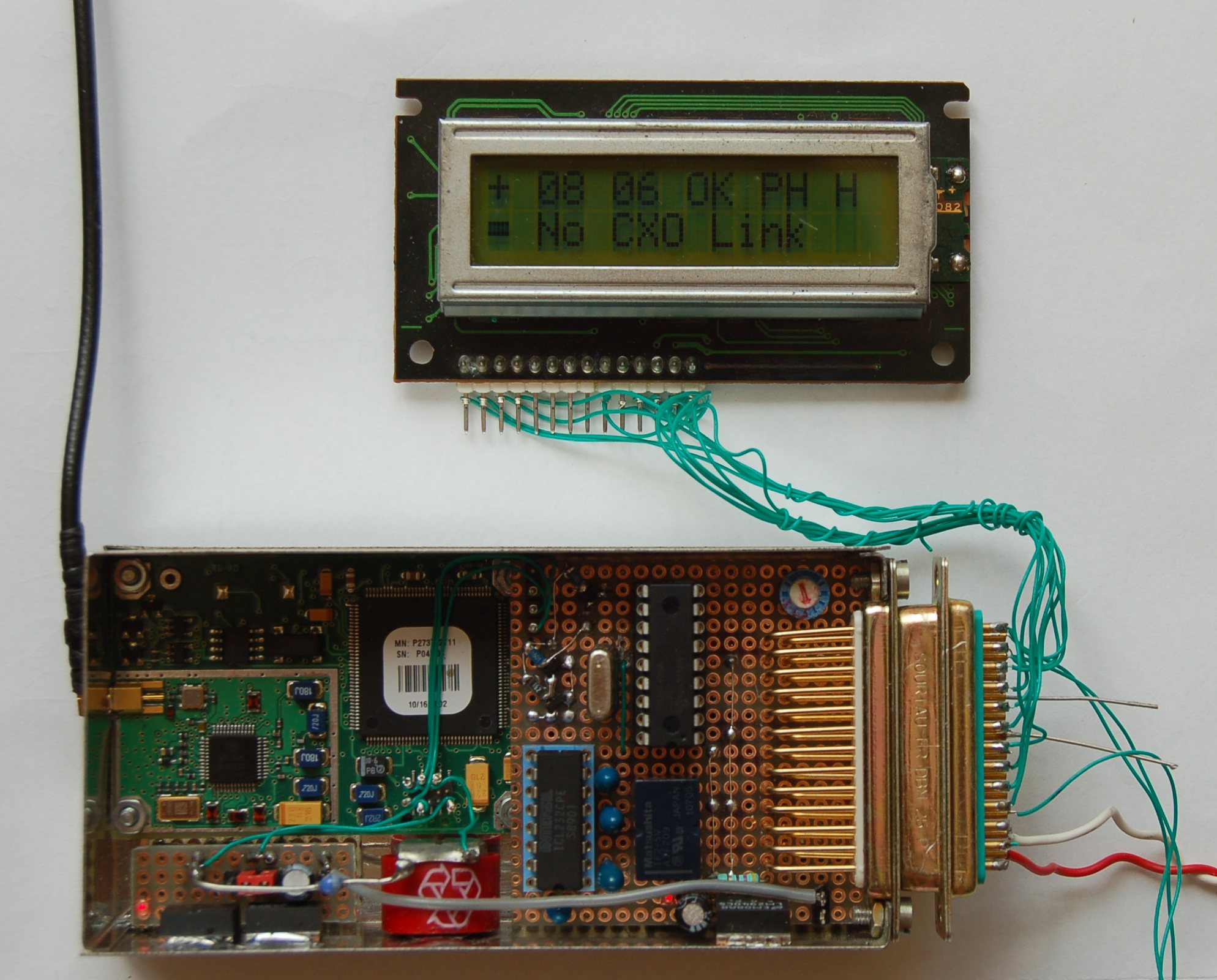
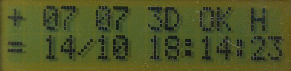
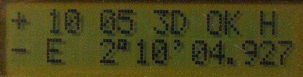
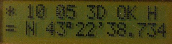
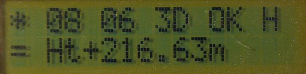
Time is displayed when at least one satellite is being tracked while latitude, longitude and height are displayed only after the GPS has switched to either 2D, 3D or Position hold status. Take care that Rockwell Jupiter does not send the NMEA 'ZDA' frame which gives date and time.
Configuration details
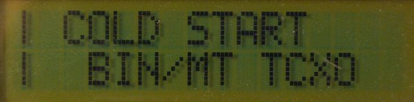
The MT12 module can be fully reseted by linking the REMOTE input (pin 17) to the -12V (pin 19) while powering up the module. A message will then be displayed and the initialization sequence will be sent to the GPS module. This has to be done after any change in the mode (binary / NMEA) option. Take care that all the GPS tables will be lost and will have to be reacquired.
When running, the REMOTE input can be used to switch the MT12 serial input from the PIC processor to any external serial application, such as the Oncore control software. This can be useful to get its status, or verify its configuration. The MT12 serial ouput can be shared between the PIC processor and the external serial application without having to be switched, thanks to the level adaptor buffering (Q5, Q6).
As previously said, the serial link can be used to connect to any external MT12+ compliant application. MT12+ data are always sent to the TX serial output (PC_RX signal). However the MT12+ module will not receive any external data until the REMOTE signal is tied to the serial RS232 negative state (-12V). This could easily be done by connecting it to the external equipment DSR serial pin. Current remote signal status is displayed on LCD ('R' letter).
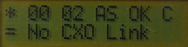
The VE2ZAZ TCXO serial output should be connected to the RB3 port (FFL_Rx signal) at TTL level. Data coming from that link will be processed and displayed provided the option is enabled which is the default case. This can be changed by writing a value other than 0 in EEPROM address 30.
The GPS module protocol can be changed from the default MT12+ binary by setting the following value in EEPROM address 31:
- 0: Oncore M12 binary with local initialization (default)
- 1: Oncode M12 NMEA with local initialization
- 2: Rockwell NMEA with local initialization
- 3: Any other NMEA provided it has previously been initialized
Here is how the information is displayed on LCD by the PIC16F648A with MT12+ binary option enabled:
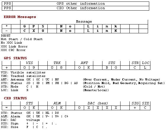
Other messages are described here.
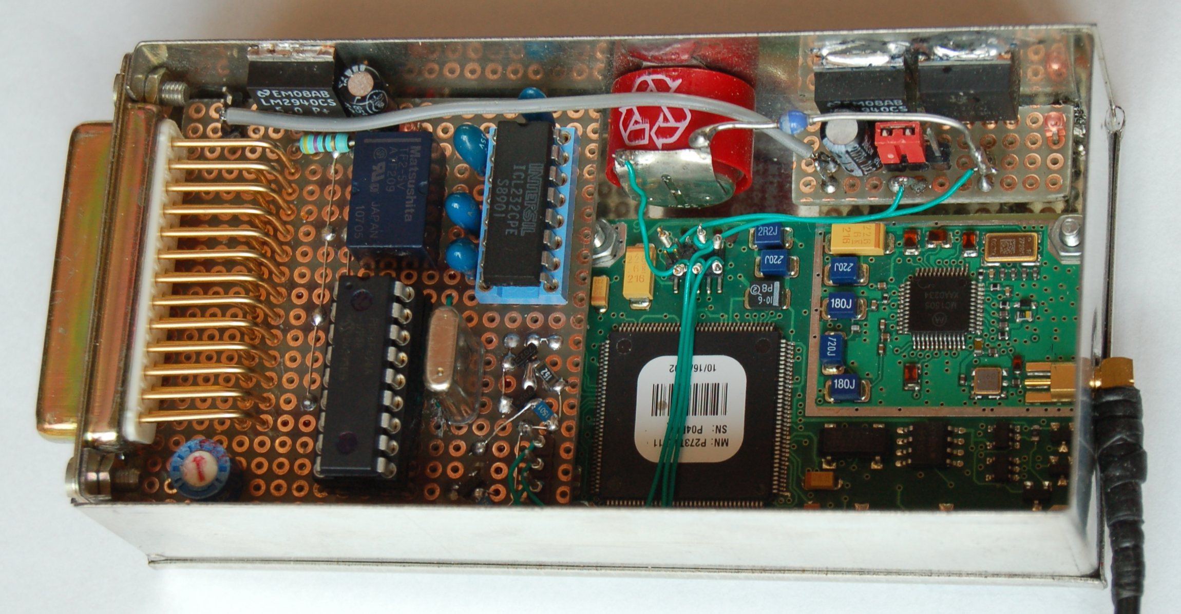
Pictures
| GPS control and display module |
 |
 |
| PIC 16F628 | Some base mode displays |
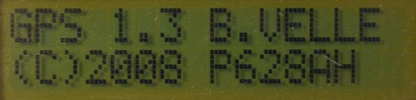 | 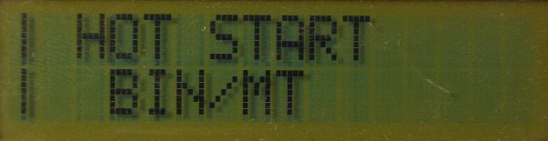 |
 |  |
 |
| PIC 16F628 | Some TCXO mode displays |
 |  |
 |  |
 |  |
| PIC 16F648 | Some Base mode displays |
 |  |
 |  |
| PIC 16F648 | Some TCXO mode displays |
| |
Last revision: 19/10/2008